we bring your ideas to life


In the Wonderful World of Transformer Manufacturing
Transformers are an important component of the power generation system, silently facilitating the transfer of power from Generation to Consumption. Behind the scenes lies a sophisticated manufacturing process that ensures their reliability, efficiency, and longevity.

The core assembly is a critical stage in transformer manufacturing, as the core is responsible for the efficient transfer of magnetic flux and minimizing energy losses.
The Cores are typically made of cold rolled grain oriented (CRGO) silicon steel lamination, designed to minimize energy losses through eddy currents. In the core assembly stage, the CRGO silicon laminations are stacked and bound together, creating a sturdy and efficient magnetic circuit. Temporary guiding bolts are used for stacking lamination. Fully mitered and step-lapped corner joints improve flux distribution, minimize losses, and reduce sound levels. The core assembly consists of the core, clamping structure, Feet, and the supporting structure for the framework to support tap and line terminals. Before starting the assembly, the core material is checked for material quality, dimensions, and any visual defects or damages. The entire assembly is done on a frame commonly known as the frame part or core channel. The frame part is made from standard IS angle, channels, or plate construction. The frame is held vertically and horizontally using tie rods. The vertical tie rods also exert adequate force on the coils during clamping to counter the stresses generated during operation. The core frame rests on its feet. The clamping structure supports the framework to route tap and line terminals.
Once the core is stacked, it is clamped together using this clamping arrangement. This ensures that the core remains tightly bound and maintains its structural integrity during subsequent manufacturing stages and throughout the transformer’s operational life.
To further reduce energy losses, the assembled core is wrapped with cotton tape and coated with an insulating varnish to minimize the effects of eddy currents within the core material.
After raising the core assembly, no-load core losses, insulation resistance, and other parameters as per IS are measured.
 The Transformer windings are primarily designed to meet, mechanical, thermal, and electrical requirements. The windings are cylindrical in shape and are assembled concentrically.
The coil winding process is an important step in the transformer manufacturing process as it involves creating the primary and secondary windings around the core. The winding process determines the electrical properties of the transformer, including its voltage ratio, current capacity, and efficiency. The winding process begins with designing the specifications of the coils viz. the number of turns, the arrangement of turns, the wire size, and the insulation requirements, based on the intended application and performance parameters of the transformer.
Generally, a copper or aluminium conductor is prepared for the winding process. The conductor wire is coated with insulating materials to prevent short circuits between adjacent turns.
The transformer winding machine is set up in dust-free and temperature-controlled environments. The machine’s configuration depends on the type and size of the transformer being manufactured. The winding machine carefully guides the conductor wire as it is wound around the former in a specific pattern and number of turns. Tension and alignment are closely monitored to ensure uniform winding. The coil formers are designed to hold the conductors in place and maintain the required coil structure.
Windings are insulated using thermally upgraded paper or Nomex. Insulation ensures electrical separation and thermal stability. Insulating materials, such as paper or polymer-based materials, are often placed between layers of winding to enhance dielectric strength and prevent short circuits. The insulation also helps to withstand the electrical stresses experienced during operation.
In larger transformers, where the winding is done in multiple layers, interleaving is done. This involves inserting insulating material between layers to further enhance insulation and maintain structural integrity.
The winding process is often done in layers, with each layer carefully laid over the previous one. This layering technique helps distribute the magnetic flux evenly and reduces the risk of electrical losses.
In transformers with tap changers, the tap changer mechanism is installed during or after the winding process. Tap changers allow for adjustments to the transformer’s turn ratio to accommodate variable voltage conditions.
Windings are thoroughly dried in the vapour phase oven and compressed with the help of a hydraulic press to get the designed height to withstand short circuit forces
Following QC checks are carried out at this stage-
- Conductor size before winding
- Electrical continuity of coil with indicator lamp
- D. and O.D. of coil
- Winding resistance of the coil
The integration of the Core and Coil is known as the CCA of the transformer. In this critical assembly stage, the core and coil are assembled together, to create a complete functional transformer. The core assembly is vertically placed on the ground with the foot plate and the top yoke of the core is removed. The limbs of the core are tightly wrapped with cotton tape and varnished.
A cylinder made out of insulating press-board/ press pan paper is wrapped on all three limbs. A low Voltage Coil is placed on the insulated core limbs. The coil is carefully inserted into the opening of the transformer core. Thi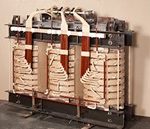 s is a delicate process, ensuring that the coil fits properly.
Proper alignment is crucial for the efficient transfer of magnetic flux.
Insulating blocks of specified thickness and number are placed both at the top and bottom of the L.V. coil.
A cylinder made out of corrugated paper or plain cylinder with oil ducts is provided over the L.V. coil and H.V. Coils are placed over the cylinder.
The gap between each section of H.V. Coils including top and bottom clearances is maintained with the help of oil ducts, as per the design.
Windings are supported by high-density pre-compressed press board and prema wood to withstand axial and radial forces generated in short circuit conditions. This ensures proper positioning of windings throughout the life of the transformer.
The Top Yoke is refilled. The top core frame including core bolts and tie rods is fixed in position.
Primary and secondary windings are connected as per the requirements. Phase barriers between H.V. phases are placed as per requirement. Connections to the tapping switch (if required) are made.
The CCA is thoroughly inspected to verify the alignment of the coil and core, proper application of insulation, and overall structural integrity of the CCA.
Only after the clearance from the QC, the core coil assembly (CCA) is placed in the vapor phase oven for drying.
The core-coil assembly is taken out of the oven and the insulation resistance and turn ratio test and other routine tests as per IS are carried out.
The Core-Coil assembly is taken for Tank up process only if the above test values are as per the design specification.
The Transformer tank fabrication and testing process is a crucial step in transformer manufacturing. The transformer tank works as a protective housing for the core and coil assembly, providing insulation, structural support, and cooling.
The tank design is determined based on the transformer specifications and application requirements. The transformer tanks are generally made of high-quality carbon steel. The steel is chosen for its strength, durability, and resistance to corrosion.
The selected steel sheets are cut into the required shapes for the tank components. This includes the tank walls, covers, and other structural elements.
The cut pieces are welded together to form the tank structure. Welding is done by a MIG welding machine, and welds are inspected for quality and strength. The pressed steel-type radiators or corrugated radiator panels are provided for the cooling of the transformer.
After w elding, the tank undergoes radiographic testing. This non-destructive testing method uses X-rays or gamma rays to inspect the tank for any defects, ensuring that the tank meets the required standards for strength and integrity.
The tank surface is treated to protect it from corrosion and environmental factors. The tank undergoes a shot blasting process to remove impurities and later the coatings of protective paint to prevent rusting. After surface cleaning, tanks are then painted internally with heat and oil-resistant paint/varnish and externally with one coat of epoxy red oxide and two coats of polyurethane paint.
Various fittings and accessories, such as bushings, valves, and radiators, are installed on the tank. (A drain valve, conservator, oil level monitor, and explosion vent are all part of the standard equipment under the transformer tank manufacturing process.)
The tank undergoes pressure testing to ensure its ability to withstand internal and external pressures. This involves pressurizing the tank with an inert gas and monitoring for any leaks. The tank must pass this test to ensure it can withstand the internal pressure variations that occur during transformer operation.
Vacuum testing is conducted to check the tank’s ability to maintain a vacuum inside, which is crucial for the proper functioning of oil-filled transformers. This test ensures the tank is sealed and free from leaks.
The completed tank undergoes a final finishing process, including painting for protection against corrosion and environmental elements. The finishing touches enhance the tank’s aesthetics and contribute to its longevity.
Transformer testing is an essential step of the transformer manufacturing process to ensure their proper operation and safety. It involves a series of tests that evaluate the electrical characteristics, insulation integrity, and mechanical integrity of the transformer.
The transformer testing process is an essential part of transformer manufacturing and quality assurance. By subjecting transformers to a comprehensive series of tests, manufacturers and users can ensure that transformers meet the required performance standards, operate safely, and maintain their reliability over their expected lifespan.


Types of Transformer Tests
The specific tests performed on a transformer depend on its type, rating, and application. However, some common transformer tests include:
Polarity test:
The polarity test determines the relative polarity of the transformer windings, ensuring that the transformer connections are proper, and the voltage output is in the proper phase relationship. Correct polarity is essential for proper operation in three-phase systems.
Insulation resistance test:
The insulation resistance test measures the electrical resistance between the windings and the transformer core and ground. This test helps detect any deterioration or damage to the insulation, which could lead to electrical breakdowns and potential hazards. A high insulation resistance indicates good insulation and low a risk of electrical breakdown.
Turns ratio test:
This test verifies that the turn ratio between the primary and secondary windings is as per specification. The correct turn ratio is crucial for achieving the desired voltage transformation. It compares the voltage applied to the primary winding with the voltage induced in the secondary winding, ensuring the transformer’s ability to convert voltages according to its design specifications.
Short-circuit impedance test:
The short-circuit impedance test measures the impedance of the transformer under short-circuit conditions, providing valuable information about the internal impedance and its ability to withstand short-circuit currents. Low impedance indicates efficient power transfer and minimal losses.
No-load loss test:
The no-load loss test measures the core losses and magnetizing current in the transformer when it is energized but not connected to a load. Core losses are due to hysteresis and eddy currents in the core while magnetizing current is the current required to magnetize the core. It helps evaluate the efficiency of the transformer and identify potential losses due to core losses or dielectric losses.
Load loss Test:
The load loss test measures the power losses in the transformer when it is connected to a load. This test provides a more accurate assessment of the transformer’s efficiency under actual operating conditions.
Load test:
This test measures the transformer voltage regulation, efficiency, and temperature rise under load conditions. Voltage regulation is the ability of the transformer to maintain a constant output voltage under varying load conditions. Efficiency is the ratio of the transformer output power to its input power, while temperature rise is the increase in temperature of the transformer windings under load.
Overall Inspection:
After completion of all individual tests, the transformer undergoes a thorough overall inspection. This inspection checks for any visible defects, loose connections, or signs of damage that may have gone undetected during individual tests.
The transformer testing process is an essential part of transformer manufacturing and quality assurance. By subjecting transformers to a comprehensive series of tests, manufacturers and users can ensure that transformers meet the required performance standards, operate safely, and maintain their reliability over their expected lifespan.
Transformer Testing Equipment
A variety of specialized equipment is used to perform transformer tests. Some of the common equipment includes:
- Megger: A megger is an instrument used to measure insulation resistance.
- Transformer bridge: A transformer bridge is an instrument used to measure turns ratio and polarity.
- Short-circuit impedance tester: A short-circuit impedance tester is used to measure short-circuit impedance.
- No-load and load test equipment: No-load and load test equipment, includes voltmeters, ammeters, power analyzers, and temperature sensors.
Transformer Testing Standards
Transformer testing is governed by various standards, such as IEEE C57.12.1, IEC 60076, and ANSI C57.12.10. These standards specify the test procedures, acceptance criteria, and safety precautions for transformer testing.
Importance of Transformer Testing
Transformer testing is crucial for several reasons:
- Ensures safe operation: Transformer testing helps identify potential defects or irregularities that could lead to electrical failures, fires, or explosions.
- Verifies performance: Transformer testing verifies that the transformer meets its design specifications and performance requirements.
- Predicts future performance: Transformer testing can provide insights into the transformer’s condition and predict potential problems that may arise in the future.
- Extends transformer life: Regular transformer testing helps maintain the transformer’s health and extend its lifespan.
